The coil is wired between terminals 2 and 5 with the contacts between terminals 1 and 2.
Potential relay troubleshooting.
Potential relay operation and testing.
The start cap is momentarily applied to the circuit then quickly disengaged.
All you have to do is touch the ends of the.
This video explains the terminal arrangement of a potential relay how to wire it up and how it works.
Replacement relays can be cross referenced for different manufacturers using convenient tables via the internet.
When used with a run capacitor a 15 000 ohm to 18 000 ohm 2 w bleed resistor should be attached to the start capacitor to prevent possible arcing when the relay contacts open.
The above procedure simply mimics the action of the potential relay.
Troubleshooting of a potential relay can be done with an ohmmeter.
My paperback and e book.
The relay does the same thing.
Whenever possible the model number on the old relay should be used when ordering a new relay.
Knowing the sequence of operation for this type of starting relay can help you diagnose confirm or rule out certain service problems.
After taking all of the connecting wires off of the potential relay measure the resistance across the 1 and 2 terminals.
Remember short out the start cap used above.
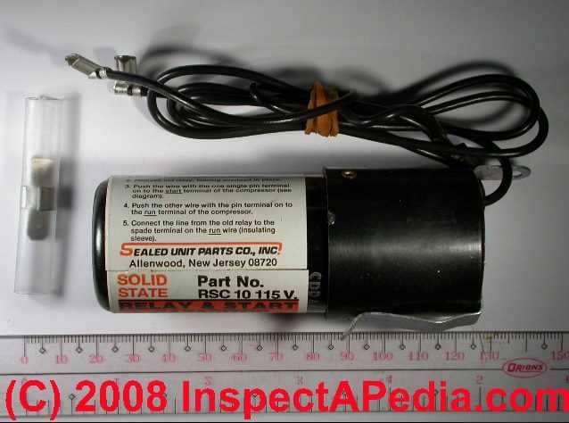
A simple ohmmeter is all that is needed to troubleshoot a potential relay.
A simple ohmmeter is all that is needed to troubleshoot a potential relay.
I ve used this procedure many times.
The relay coil is across terminals 2 and 5 while the relay contacts are across terminals 1 and 2.
It s probably a bad potential relay.

