Rfid Door Lock Block Diagram

Simple Rfid Based Door Lock Using Arduino

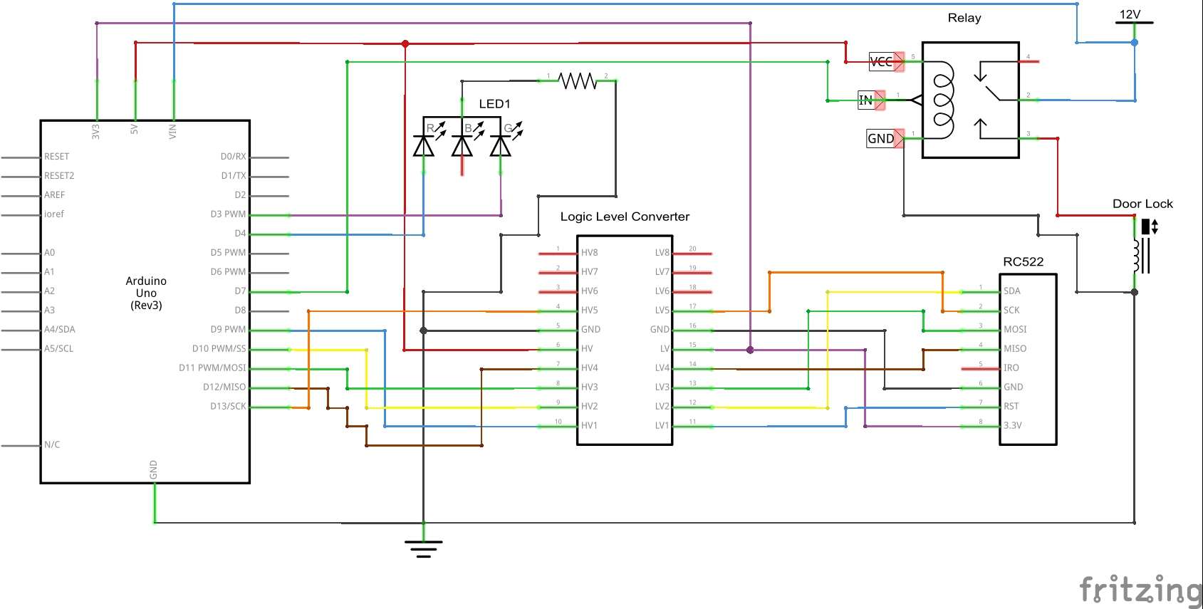
Arduino Rfid Door Lock Project Using Arduino Uno Rfid Reader Em 18 And Relay Module

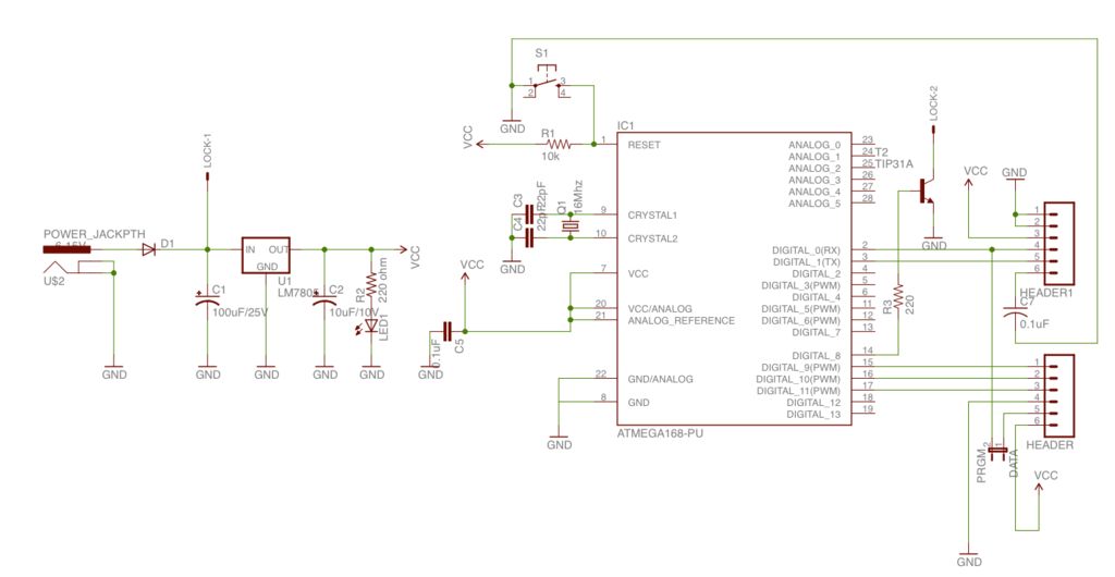
Schematic Diagram Of Door Lock System Download Scientific Diagram

Arduino Rfid Door Lock Access Control Project Access Control Control Arduino

Figure 1 From Survey On Various Door Lock Access Control Mechanisms Semantic Scholar

Rfid Based Door Lock System Using Avr

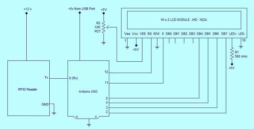
This rfid based security system is based on micro controller at89c52 and comprises a rfid module a lcd module for displaying the status and a relay for opening the door.
Rfid door lock block diagram.

Coolest Door Lock Ever Arduino Project Hub
Rfid Based Automatic Door Lock System With Arduino
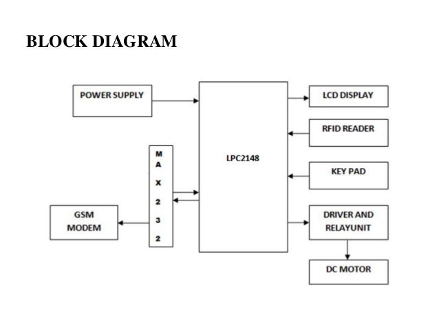
Locker Opening And Closing System Using Rfid Password And Gsm
How To Make A Arduino Controlled Rfid Keyless Entry Door Lock

Make Your Own Arduino Rfid Door Lock Arduino Leds

Block Diagram Of The Rfid System Download Scientific Diagram
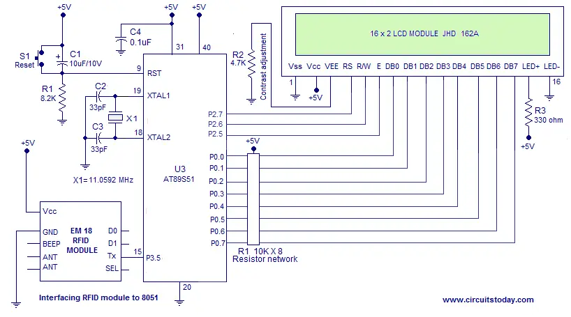
Rfid Door Access Control System Using 8051 Microcontroller Ece Project

Rfid And Keypad Door Lock And Alert System Using Arduino Arduino Project Hub

Rfid Door Lock Semantic Scholar

Rfid Door Lock System Hackster Io

Pdf A Digital Security System With Door Lock System Using Rfid Technology

Rfid Basics And Rfid Module Interfacing With Arduino
Adding A Buzzer Leds Next Step Is To Add A Buzzer And 2 Leds To Simulate A Controlled Access System Please Review Arduino Rfid Arduino Arduino Projects Diy
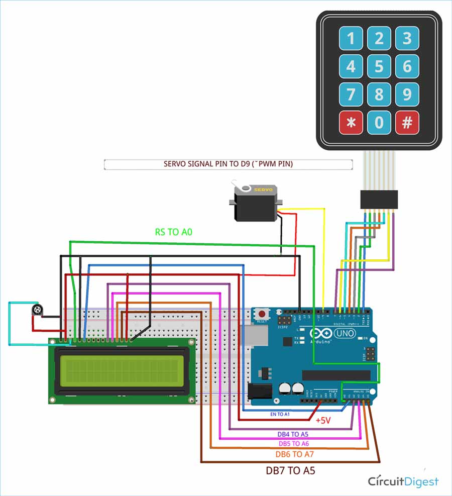
Digital Keypad Security Door Lock Using Arduino

Door Access Control With Arduino And Rfid Rc522 Arduino Tutorial Electronica Tecnologia Proyectos

Solenoid Door Lock Contol Rfid Arduino Youtube
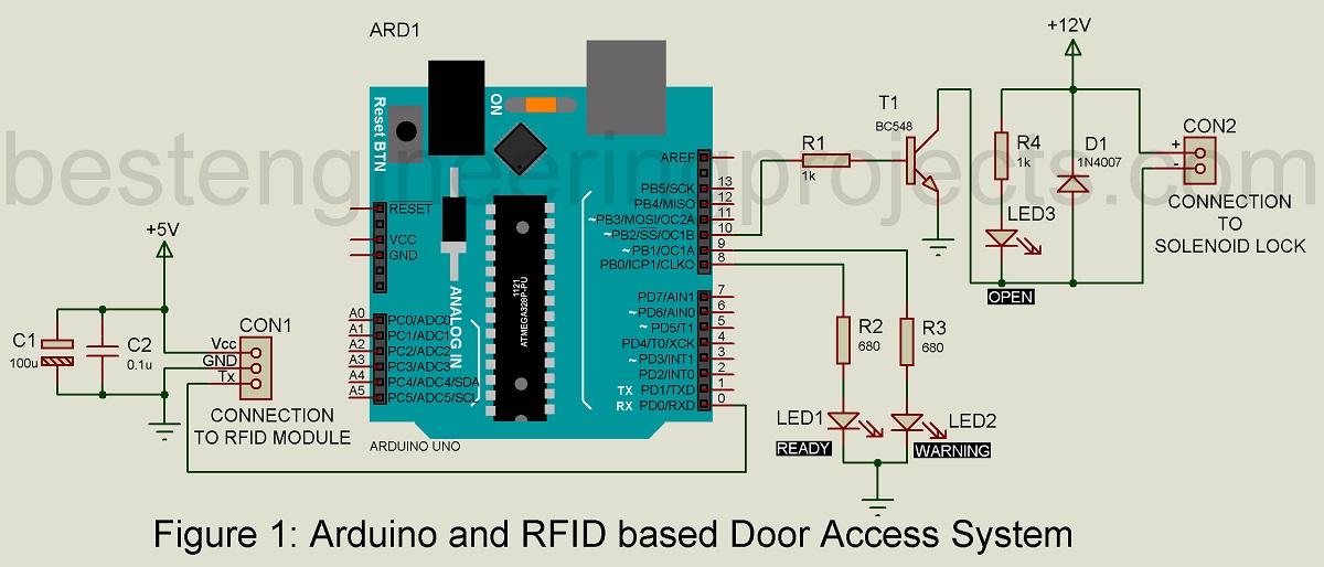
Arduino And Rfid Based Door Access System Engineering Projects

Arduino Rfid Door Lock Arduino Bluetooth Arduino Arduino Projects
Https Encrypted Tbn0 Gstatic Com Images Q Tbn 3aand9gcsn0l87mpgbmxic53k6u5g3ghwckdljfxk4rou8u1g2pe6japdf Usqp Cau

Digital Door Lock Using Arduino Circuit Diagram Digital Door Lock Arduino Arduino Circuit
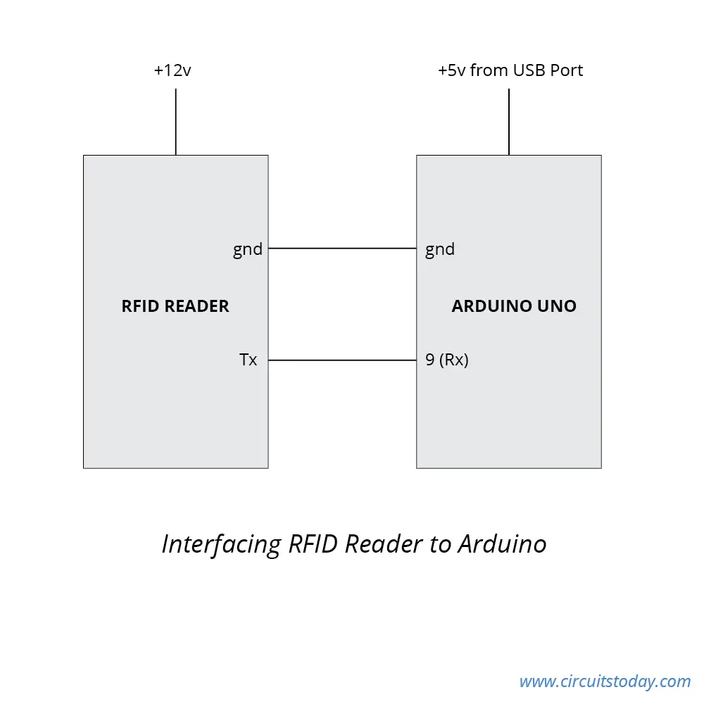
Interfacing Rfid With Arduino How To Read Rfid Cards

Diy Smart Lock With Arduino And Rfid Makeuseof
Results Page 174 About 6 Building Blocks Searching Circuits At Next Gr
Rfid Door Lock Learn Circuitrocks
Source : pinterest.com
